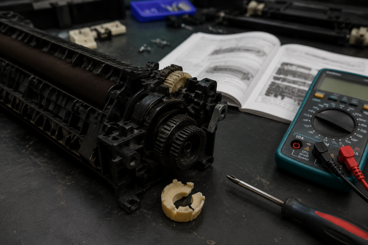
A failing fuser assembly can stop your printer cold with error codes like 50.1, cause smudged or wrinkled pages, or even emit a burning smell. This guide walks you through diagnosing the exact issue — from simple gear wear to failed thermistors — and gives you a clear path to fix it yourself with basic tools and low-cost parts.
What’s Happening — Symptoms in Detail
Your printer just broke, and you’re staring at a cryptic error code or a page that looks like a disaster. Here’s exactly what you’re likely experiencing:
Error Codes on Screen: Many brands show specific codes. HP printers often display 50.1 Fuser Error or 50.2 Fuser Error. Brother devices may flash Error Fuser or Error Fuser Overheat. Canon units show Error 5200 or Error 5C00. Samsung printers may show Fuser Error 0 or Fuser Jam 0. These codes mean the printer cannot detect the fuser correctly, or it’s reporting a temperature fault.
Visual Page Problems: Even before an error code appears, you might see:
- Smudged Toner — the toner isn’t fused to the paper and rubs off when touched.
- Wrinkled or Creased Paper — the fuser rollers are gripping unevenly.
- Vertical Lines or Ghosting — a previous image reappears faintly.
- Paper Jam in Fuser Area — the paper stops halfway out the rear of the printer.
When It Happens:
- On Startup — the printer runs its self-check and immediately throws an error. This indicates a thermistor or heater failure.
- During a Print Job — after a few pages or at the very start of a job. This often means the fuser is not heating up fast enough.
- After a Paper Jam — you cleared a jam, but now the fuser won’t reset. The jam may have damaged the fuser roller or its drive gears.
- After a Firmware Update — rare, but possible if the update changes fuser temperature parameters.
How It Progresses:
- Sudden Failure — one moment it prints fine, the next it’s dead. Likely a thermistor or thermal fuse.
- Gradual Worsening — pages get slightly more smudged over weeks, then suddenly error out. This points to worn fuser rollers or degraded bushings.
A burning smell (like hot plastic or ozone) indicates the fuser is overheating or has a short circuit. Stop using the printer immediately.
How to Diagnose the Problem Step by Step
Follow these steps in order. You’ll need: a #1 Phillips screwdriver, a flashlight, and a multimeter (optional for advanced checks).
Power Cycle & Error Code Check — Unplug the printer for 5 minutes. Plug it back in and power on. Does the same error reappear after startup? If yes, proceed. If the error is gone, it may have been a thermal glitch, but still check the fuser visually.
Visual Inspection (Quick Check) — Open the rear access door (often called the fuser door). Use a flashlight to look at the fuser unit. Normal: the fuser roller (top shiny silver roller) is smooth, no cracks, no melted toner. Abnormal: you see chunks of toner stuck, a white line across the roller, or a tear in the fuser film (looks like a dark slit). Also check for any small plastic gear visible at the end of the fuser — if it’s missing teeth or cracked, that’s your problem.
Rotate the Fuser Roller by Hand — With the printer off, locate the drive gear on the fuser assembly. Using a flathead screwdriver (or your finger if safe), try to rotate it clockwise. Normal: it turns smoothly with light resistance. Abnormal: it stops hard (jammed), spins freely with no resistance (broken internal gear), or makes a grinding sound.
Thermistor Continuity Test (Advanced) — If you have a multimeter, remove the fuser assembly (see repair process steps). Locate the thermistor — a small glass bead or metal disc with two wires, usually touching the fuser roller. Set your multimeter to ohms (200k range). Measure across the thermistor wires at room temperature. Normal: reading between 100k and 500k ohms. Abnormal: 0 ohms (shorted), infinite ohms (open circuit — failed), or a reading that doesn’t change when you warm the thermistor with your fingers.
Thermal Fuse Check — Many fusers have a thermal fuse (looks like a small white or yellow cylinder with two leads). Set multimeter to continuity (beep). Touch probes to each end. Normal: beeps (continuity). Abnormal: no beep (fuse blown — fuser is dead).
Paper Path Test — Remove the fuser and manually feed a piece of paper through it (turn the gear by hand). Normal: the paper passes straight through without wrinkling or stopping. Abnormal: the paper jams, folds, or requires excessive force. This indicates a bent fuser roller or broken internal guide.
Why This Happens — Root Cause
Why does the fuser assembly fail? Understanding the engineering helps you avoid repeat failures.
Thermistor Failure: The thermistor is a temperature sensor that tells the fuser heater when to start and stop. It’s a small glass-encapsulated NTC (negative temperature coefficient) resistor. Over thousands of heat cycles (each print job), the glass can crack, or the leads can fatigue. When it fails, the fuser either never heats up (cold fuser error) or overheats (burning smell + fuser error).
Thermal Fuse Blow: The thermal fuse is a one-time safety device. If the thermistor fails and the fuser overheats past a threshold (typically 220°C), the fuse blows open. It’s a common secondary failure. Some printers also blow this fuse during a power surge.
Fuser Roller Wear: The upper fuser roller has a Teflon coating. After tens of thousands of pages, this coating wears thin, exposing the aluminum core. Toner sticks to the bare metal, causing smudges and eventual paper jams. The lower pressure roller (rubber) can also develop flat spots from sitting idle for months, leading to wrinkles.
Gear and Bushing Wear: The fuser drive system uses plastic gears and bushings. Over time, heat and friction cause the bushings to oval out, putting side load on the gears. The upper fuser roller gear (Part #1: Upper Fuser Roller Gear with Bushing) is a known weak point on HP LaserJet 1320/3390 and Brother HL-2270DW models. When this gear cracks or its bushing wears, the fuser stops turning, causing a fuser jam error.
Paper Dust and Debris: Cheap or recycled paper sheds more dust. This dust accumulates inside the fuser, especially on the thermistor and fuser film. It acts as an insulator, causing the fuser to overheat or not heat correctly.
User Abuse: Pulling jammed paper out forcefully can rip the fuser film or bend the fuser roller frame. Always remove jammed paper in the direction of paper travel, not backwards.
Part Number Cross-Reference: For HP printers, the fuser assembly is often a single unit (e.g., HP Fuser 110V for LaserJet P1005). For Brother, it’s often called a fuser unit (e.g., Brother BU-220CL). Inside, the replaceable wear parts include the upper fuser roller gear (Part #2: JC66-03080A / JC61-03755A Upper Fuser Roller) and bushings.
Can You Fix It Yourself?
- Difficulty Level: 3 out of 5. You’ll need patience with small clips and ribbon cables. No soldering required.
- Time Required: 30–60 minutes for the first time. Experienced users can do it in 20 minutes.
- Skill Level Needed: Comfortable with a screwdriver and following disassembly steps. No electronics soldering — but you will unplug connectors.
- Risks:
- Electric Shock: The fuser runs on high voltage (110V or 220V). Always unplug the printer and wait 5 minutes for capacitors to discharge.
- Breaking Plastic Clips: Fuser housings use fragile tabs. Use a plastic spudger or flathead screwdriver carefully.
- Damaging the Thermistor: The thermistor is delicate; don’t bend its wires or scratch its glass bead.
- Incorrect Gear Installation: The upper fuser roller gear must line up with the drive gear. If misaligned, the fuser won’t turn.
- Tools Required:
- #1 Phillips screwdriver (small)
- Flathead screwdriver (small, for prying)
- Tweezers (for small connectors)
- Multimeter (optional, for testing thermistor/fuse)
- Flashlight
- Clean lint-free cloth
- Thermal paste (if the new thermistor doesn’t have it pre-applied; check guide for your model)
Cost Breakdown — DIY vs Professional
DIY Cost:
- Part #1: Upper Fuser Roller Gear with Bushing — $1.02
- Part #2: JC66-03080A / JC61-03755A Upper Fuser Roller — $1.13
- Total for both parts: less than $3, plus shipping (often $3–5). If you need the whole fuser assembly (for a non-modular design), prices range from $15 to $60 on eBay or Amazon.
- Add $3–10 for thermal paste if needed.
Professional Repair Cost:
- Typical repair shop charges $50–150 for diagnosis plus labor. They will often replace the entire fuser assembly at a cost of $80–200 (parts + labor).
- Manufacturer out-of-warranty service: $100–300 flat fee (often just a replacement printer).
When to Skip DIY:
- If your printer is over 5 years old and low-end (e.g., $99 HP DeskJet), replacing the fuser assembly on a budget printer may cost more than a new printer. Consider buying new.
- If you’ve opened the printer and found melted plastic, cracked frame, or severed wires — the damage is likely too extensive.
- If you’re not comfortable disassembling printers, or you need the printer for urgent work, paying a repair shop is faster.
Comparison: For $3 in parts, you can fix a gear/bushing issue that a shop would charge $100+ for. That’s a 97% savings.
Repair Process Overview
The exact steps vary by model, but this general process applies to most HP, Brother, Canon, and Samsung printers with a removable fuser assembly.
Unplug the Printer — and wait 5 minutes for capacitors to discharge. Lay the printer on its side or front for easier access.
Remove the Rear Cover or Fuser Door — Usually held by two screws at the back. Set aside.
Disconnect the Fuser Connectors — Look for two harnesses: one for the heater (thicker wires) and one for the thermistor (two thin wires). Carefully unplug them by pulling the connector, not the wires.
Remove the Fuser Assembly — It is typically held by two to four screws or snap-tabs. Slide the fuser out as a unit. Note: some models require removing a metal shield or a paper guide first.
Disassemble the Fuser — Place the fuser on a clean towel. Remove the end caps and side covers (usually clips). Note the position of any washers or springs.
Replace the Worn Parts —
- Upper Fuser Roller Gear with Bushing: Pry off the old gear with a flathead screwdriver. Press on the new one (Part #1) until it clicks into place. Make sure the bushing seats fully.
- Upper Fuser Roller: If the roller itself is damaged (tears or melted toner), replace it (Part #2). Slide out the old roller by removing the E-clip or spring on one end. Slide in the new one, reattach the clip.
- Thermistor: If your multimeter test showed it’s faulty, desolder or unscrew the old thermistor and replace with the same type (order a compatible one, not listed here). Apply a tiny dab of thermal paste to ensure good contact.
Reassemble the Fuser — Reverse the disassembly. Be careful not to pinch wires. Ensure all gears rotate freely before closing.
Reinstall the Fuser Assembly — Slide it back into the printer, secure with screws, reconnect the connectors. Double-check the cable routing — wires must not touch the fuser roller.
Replace the Rear Cover — and plug the printer in.
Common Mistakes:
- Forgetting to apply thermal paste on the thermistor (causes false temperature readings).
- Installing the gear upside down or on the wrong shaft (the drive gear has a specific orientation).
- Leaving plastic shavings from broken clips inside the printer (can cause short circuits).
- Not aligning the fuser frame properly (will jam paper).
After the Repair — Testing & Verification
Power On and Wait — After reassembly, plug in the printer. It will go through its startup cycle. Look for any error codes on the screen or blinking LEDs. A normal startup is: all lights flash briefly, then the printer goes to Ready.
Test Print — Send a single test page from your computer or use the printer’s internal test page (often hold the Go button for 3 seconds). Check: the page should be clean, no smudges, no wrinkles, and the toner should be dry to the touch.
Monitor the First 10 Pages — Print 10 pages of the same test pattern. Watch for:
- Fuser Error Code — If it reappears after 3–4 pages, the thermistor may still be misaligned or the thermal fuse blew again.
- Uneven Fusing — One side of the page smudges while the other is fine. This indicates uneven pressure, possibly a bent roller.
- Noise — Grinding or clicking sounds while printing mean a gear is stripped or the bushing is not seated.
Check for Burning Smell — After the first print, sniff the rear vent. A faint new-plastic smell is normal. Any strong chemical or burning odor means the fuser is overheating — unplug immediately and recheck the thermistor connection.
Do a Two-Sided Test (if applicable) — If your printer supports duplex, print a 2-sided document. The paper path through the fuser is longer; any misalignment will show up as a jam.
Final Verification: Run a calibration or cleaning cycle from the printer’s menu (if available). This cycles the fuser to its full temperature range and confirms stable operation.
Parts You’ll Need
Here are the parts that match this repair. Click the link to check the current price on AliExpress.
| Product | Price |
|---|---|
| Upper Fuser Roller Gear with Bushing … | $1.02 |
| JC66-03080A JC61-03755A Upper Fuser R… | $1.13 |
Prices and availability are subject to change on AliExpress.